RE: Re: enclosing the genset
I am sorry these are so long, hope it is not too boring or weird.
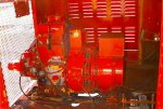
Thanks for all the support, I have not enclosed the set from the rear yet, but I will partially enclose it in a semi-permanent way, just like the front. I figure that sitting still, the thing is open enough with the inboard and outboard areas open, and right now I do not plan to use it while moving.
If I did want to generate while moving, I would prefer to force-cool it. -That is why I was after Wreckerman's fan off that chemical shelter trailer.. but who knows, I need to go look at the pics again and maybe ask for one of the GM compressors, they look like the A6 model, which has more displacement than most of the Sanden, etc. models today. It might have to be rebuilt with the R134 seals though, not too sure. In the end I would rather use the engine for a/c while moving, although 5-10HP to the GM kompressor is a fair chunk of the 130 or so that the engine makes!
About the flourescent lights and their evil harmonics, that has to be definitely addressed. I have to first do scientific measurements using a curent transformer and an oscilloscope and see how the theory compares to the reality.
About the military generators, I believe that if the sets are brushless and capacitor-regulated, they would behave the same. (where are the diagrams - in some other thread perhaps. I wonder if a brush-and-slip-ring unit would suffer the same hardship? Likely yes, because the nasty curent spikes would still cause the same I^2R losses. So, the military stuff is going to be alike for the most part.
By the way, at home we do not have an issue with loads like this because the electrical service is 100 or 200 amps, not 25 as with the generator.
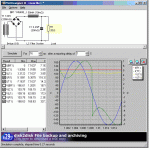
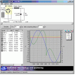
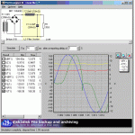
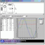
I did some dreaming on this and it might be possible, using the simulations as though they are fact, in lieu of measurements which will take me a couple weeks to get to, to deal with the pulses without impacting the 60Hz waveform. Let's keep in mind I am using sims for the discussion, until i am able to measure.
At first, I was thinking to find a way to reduce the pulses while leaving the normal power alone. How do you cancel out capacitance? with inductance! But if I match the inductor (choke or coil whatever you want to call it) to the characteristics of the spike, then it might become a series resonant circuit and this would cause some spectacular destruction of the lamp ballasts (high reactive voltages >1000V would short out the diodes). There is possibly some value of inductance, selected for an imperfect match at the resonant frequency, that would help but I need the real measurements to calculate that. Also, the pulses from the ballasts change width with voltage, as the ballasts have a regulator inside that keeps the power fairly constant.
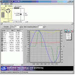
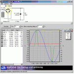
The images below show a possible modification for inside the ballast itself, unknown how it would work except that it would reduce the harmonic spike amplitude and frequency and possibly have side effects on the regulated part of the ballast, maybe heating it because although the DC voltage would be lower, the current woud become higher. Also notice the resonant current (green) is about twice the 60Hz frequency in the first one. This could also cause some distortion of the AC waveform, but it looks pretty good here. Even harmonics are not as bad as odd harmonics. I don't think it is a good solution though, and look at the very fast current reversal in the middle of the waveform. The inductor would also be as large as the size of a 3" cube. From top to bottom, notice how the less inductance is inserted into the ballast's power supply, the more the curent waveform becomes like the stock-standard case of the present inexpensive ballast design. These general curves apply to most any rectifier-type power supply.
It was suggested to add capacitance to the AC side of the circuit. Adding it in parallel in enough capacity to supply the 35 amp spike would cause a very large power factor (voltage and current out of phase) issue. Adding it in series with the lamp ballasts to limit the current to 5 amps (132uF/20 Ohms reactive @ 60Hz) would reduce the voltage to about half and the lamps would not light.
So, it's not a simple issue, I hope I can find a solution. I don't want to go with wasteful, heat-producing light bulbs or with "regular" flourescent ballasts. Regular ballasts might have an acceptable power factor, especially with two lamp ballasts where one lamp leads and one lamp lags the incoming AC voltage waveform. But i have already spent the $ to put these in. A last resort would be to go to the magnetic 2-lamp ballasts, requiring the lamps and the ballasts to be changed, keeping the fixtures. Those are fussy about starting in cold temperatures and on generator power.
One possibility is a "line filter", a so-called low-pass filter for AC power. I might try this. It would be easy to just open the power distribution panel and insert it into the live circuit there. I have no way to simulate that.. anyone got a decent graphical simulation package? This one is free but limited. It's for designing high voltage power supplies for vacuum-tube amplifiers.
In the next installment, a friend is bringing me a box of used oven elements next week for the load bank test, and I'll have to scare up or possibly make a wideband current transformer to get the real data.


