• Steel Soldiers now has a few new forums, read more about it at: New Munitions Forums!

  • Microsoft MSN, Live, Hotmail, Outlook email users may not be receiving emails. We are working to resolve this issue. Please add support@steelsoldiers.com to your trusted contacts.

New M-1083 owner. So, here we go!!

Ronmar

Well-known member
3,327
6,704
113
Location
Port angeles wa
You need to get it up to op temp so the thermostat opens. This will push the trapped air in the upper pipe on into the raditor where it can find its way up to the expansion tank… keep track of the sight glass thru a couple of heat cycles in case you need to make up the level when the air purges…
 

Ronmar

Well-known member
3,327
6,704
113
Location
Port angeles wa
As we progress along, I have a question:

1) Can I drive the truck with the front driveshaft removed? Like normal on the road driving?
Its all wheel drive. If the front driveshaft is removed all the torque will escape there. And the truck will not move. You can lock the center differential by entering mode and you can drive this way, but you are limited to 5th gear…
 

Ronmar

Well-known member
3,327
6,704
113
Location
Port angeles wa
Depends on exactly where the air is coming from… Where exactly is the air coming from? All the brake venting should be plumbed outside the cab. The treadle valve vent and the park valve vent are tied together and exit thru a port in the floor right in front of the radiator. If the treadle was bypassing to vent while pressing the pedal(dirty or failing valve), that is where the air should be going…
 

RRaulston

Well-known member
220
541
93
Location
Sahuarita, Arizona
So my left rear turn signal isn't working. On a visual inspection I find an unplugged wire! Thinking it can't be that simple, I plug it in, and the light comes steady bright. note the turn signal isn't activated yet. This explains why the PO disconnected it I'm assuming. I printed out the schematic and trace the LH turn and stop (LH461) to K30. Could K30 be stuck closed? I'll be checking that soon. too cold to go out.... Just learning to read the schematics....
 

Ronmar

Well-known member
3,327
6,704
113
Location
Port angeles wa
So my left rear turn signal isn't working. On a visual inspection I find an unplugged wire! Thinking it can't be that simple, I plug it in, and the light comes steady bright. note the turn signal isn't activated yet. This explains why the PO disconnected it I'm assuming. I printed out the schematic and trace the LH turn and stop (LH461) to K30. Could K30 be stuck closed? I'll be checking that soon. too cold to go out.... Just learning to read the schematics....
Or something further up the circuit is telling K30 to energize… the lighting circuit is a real fun one, enjoy:)
 

RRaulston

Well-known member
220
541
93
Location
Sahuarita, Arizona
OK Here is the left taillight relay.

Screenshot 2022-12-14 191200.png

So if 85 and 86 complete the circuit, the electromagnet energizes and closes 87 sending power through it? So 3047 or 461B could be energizing it, right? I can't tell if there is a left blinker relay energizing this relay. The right turn signal works fine. E3 appears to be a 2 way switch? Gonna keep at it....
 

Ronmar

Well-known member
3,327
6,704
113
Location
Port angeles wa
OK Here is the left taillight relay.

View attachment 886299

So if 85 and 86 complete the circuit, the electromagnet energizes and closes 87 sending power through it? So 3047 or 461B could be energizing it, right? I can't tell if there is a left blinker relay energizing this relay. The right turn signal works fine. E3 appears to be a 2 way switch? Gonna keep at it....
Well sort of:) Anyplace you see TB2, thats ground. Pin 85 on these relays is always connected to ground. Pin 86 will always have the + voltage applied. When voltage and ground are pplied, the coil pulls in and connects pin 30 to 87. When you de-energize the coil it shifts the connection so 30 connects to 87A.

E3 is a junction point. So those 4 wires are potential inputs. One is probably an input from the brake circuit, one is probably an input from an inter-vehicular cable port on the front bumper, one is probably the left turn signal input, and one may be an output to the rear towing/intervehicular port… you have to trace them out on the drawings to see what they are for.
 

RRaulston

Well-known member
220
541
93
Location
Sahuarita, Arizona
Well sort of:) Anyplace you see TB2, thats ground. Pin 85 on these relays is always connected to ground. Pin 86 will always have the + voltage applied. When voltage and ground are pplied, the coil pulls in and connects pin 30 to 87. When you de-energize the coil it shifts the connection so 30 connects to 87A.

E3 is a junction point. So those 4 wires are potential inputs. One is probably an input from the brake circuit, one is probably an input from an inter-vehicular cable port on the front bumper, one is probably the left turn signal input, and one may be an output to the rear towing/intervehicular port… you have to trace them out on the drawings to see what they are for.
wow, great info. You are a good teacher! So, let's reassess:

Screenshot 2022-12-14 191200.png

1922 should be +24v as it comes from circuit breaker 43. 86 is always hot and is simply supplying +24v to 4 circuits at junction E3. TB2 is ground. So, I should be chasing 87/461T as to why it constant hot, right?! And if 85 is ground and 86 hot, what keeps 87 from making contact? Would something like the blinker switch ground 3047 when activated? I will be going to the printers this week to print the schematics in a large format. I can't read the 8.5x11 very well....
 
Last edited:

Ronmar

Well-known member
3,327
6,704
113
Location
Port angeles wa
Anything connected to TB2 in any of these drawings is hard connected(not switched) to ground. If pin 86 has voltage, then this relay will energize, passing power from pin 30 to pin 87. 86 is an input. If it has voltage on it, it is coming in on one of those 4 lines connected to junction E3. Pin 86 should only receive power when you want a brake or turn signal lit because that is what this relay does when its coil is energized…
 

Ronmar

Well-known member
3,327
6,704
113
Location
Port angeles wa
So the light issue was the relay. Replaced it and all good. Something interesting is I seem to have some 5 pin relays in a 4 pin socket..... So using a 5 in a 4 is ok but not a 4 in a 5?? I also started the changeover from breakers to spade fuses...
Yep, you can use 5 pins everywhere, that way you only need two types(12 and 24v coils). A 4 pin where a 5pin should be will indeed cause some issues:)
 

RRaulston

Well-known member
220
541
93
Location
Sahuarita, Arizona
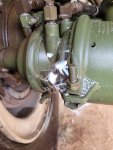
What a day. I replaced the trailer and park brake valves on the dash today. Uh... There is like no room in there! That had to be one of the most frustrating things I've done so far. Now that those two huge leaks are gone, I killed the engine, released the brakes and heard more hissing. Got out the soapy water and found this. IN 3 different pots! Ugh... Isn't the diaphragm replaceable? It's the larger one leaking. I can still hold 120psi pressure. I also put a kit in the air dryer. It's the original finned unit and works fine.


20221218_144418.jpg
 
Top
AdBlock Detected

We get it, advertisements are annoying!

Sure, ad-blocking software does a great job at blocking ads, but it also blocks useful features of our website like our supporting vendors. Their ads help keep Steel Soldiers going. Please consider disabling your ad blockers for the site. Thanks!

I've Disabled AdBlock
No Thanks