• Steel Soldiers now has a few new forums, read more about it at: New Munitions Forums!

  • Microsoft MSN, Live, Hotmail, Outlook email users may not be receiving emails. We are working to resolve this issue. Please add support@steelsoldiers.com to your trusted contacts.


Oil seal mod. for 3053 input shaft

Jeepsinker

Well-known member
5,341
329
83
Location
Dry Creek, Louisiana
That would be super tiny. And then the spindle gets real thing near the only area that sees any stress on the whole part.

Let's see what you got. I don't want to rain on your parade unjustly.
 

rustystud

Well-known member
9,071
2,388
113
Location
Woodinville, Washington
View attachment Scan0024.pdf
Looks like M-Series Rebuild also offers an oil seal mod: http://www.mseriesrebuild.com/photo_gallery2.htm Looks like they maybe epoxied something to retain the seal????
Yep, it's epoxied it in. I would never use that piece. I have seen parts that where epoxied in transmissions before. They have a tendency to come loose and destroy the bearings. Especially the small needle bearings. I had a case that someone tried to repair a crack with by using epoxy. The epoxy came loose and destroyed the input to output bearings and the idler shaft bearings. All small needle bearings. There was another one that they tried to repair the shifter rails with epoxy. Same results.
 

gringeltaube

Staff Member
Super Moderator
Moderator
Steel Soldiers Supporter
6,882
2,260
113
Location
Montevideo/Uruguay
Yep, it's epoxied it in. I would never use that piece. I have seen parts that where epoxied in transmissions before. They have a tendency to come loose and destroy the bearings. Especially the small needle bearings....
Agreed, but... they are saying it is holding up fine, and for years now? I have heard only good comments from Mr. Talbert (M-Series Rebuild) and I simply can't imagine that he would put at risk his good reputation by installing something that wasn't well tested before?

If so, that's a piss poor way to do it.
Garrett, there might be a way to do this without relying too much on epoxy... What about some machining to the original part and then inserting (light press-fit) a custom made seal-carrier, like shown below. I'm not sure what kind of sealant I would use; probably anaerobic like Loctite#518 or equivalent.
In case that this inserted piece ever popped out of its seat - or simply started leaking, the whole retainer would again work as designed from factory. No epoxy chips floating around and the loose insert with its seal wouldn't go too far, either.

To comment on the pictures above, the question remains how good the sealant/epoxy/glue would withstand the combined effect of oil and high temperature, over years of service.


G.
 

Attachments

Last edited:

gringeltaube

Staff Member
Super Moderator
Moderator
Steel Soldiers Supporter
6,882
2,260
113
Location
Montevideo/Uruguay
True, but it all depends on how much material needs to be removed- and where...

I'm always open to new (and less expensive) ideas, to solve this old problem. Ideally, we would end with a still reliable solution, for say $100 - or less.


G.
 

brianp454

Member
572
11
18
Location
Portland, OR
Spicer 3052 3053 3053A Bearing Retainer Seal Considerations

To start with, I wasn’t planning to come out with this until the 1[SUP]st[/SUP] of the year, so I’m not quite as prepared as I’d like. It is pushing me to delve into this about a month earlier than planned. There’s suddenly a bunch of interest even though it’s been quiet for a long time. I was starting to think this was so stale that it really did not have bone-fide interest. I think what interest there may or may not be remains to be seen.

Some of you know that I suffered intermediate axle differential failure recently and it took a lot effort to complete (and the week prior to a weeklong business trip to Asia with the fridge dying the same week). And it wouldn’t have gotten sorted out at all if not for some generous help from friends (Thank You Ed for many hours of labor and Stephanie for having an axle from a bobber!). There’s always a distraction…

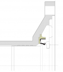
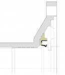
Similar to gringeltaube, I made a solid model of the existing part as a starting point. Looking at the wall thickness and the constraints on positioning the seal, it looked like there wasn’t a way to get a seal in there (especially assuming a big thick seal such as the front crank seal on the small block Chevy as it is very common, note this was one of my early choices). If you look at the cross-section from gringeltaube’s model it’s obvious it will not work with the big seal assumption (Benny Hill definition).

And I thought that was the end of it and I considered welding in an insert, doing a two-piece design with a weld joint, an interference fit design, etc. Then I got creative on a different path and started looking at different sized seals, ordering them, ordering more, re-modeling different scenarios, weighing the constraints, etc. Much as you would expect, I found some suppliers re-part numbering other manufacturers seals or substituting similar ones. After sorting through all that, I found three seals that are readily available (again, that is a must). And between $5-10 bucks each or so. Two of the seals would work fine and one of them I would prefer not use, although it might be OK, I just don’t have experience with that particular seal design (even though I know from cross-references that it is used in other auto applications successfully). I called one of the two BEST and would prefer to use it, again, the second choice seal should also work. I can order the most preferred seal and get several in 2-7 days. So, the availability issue is sorted out. If the thing leaks because it’s brittle 25 years from now, anyone should be able to get a replacement with reasonable effort. If any of us are around then to have that “problem” I’d consider them lucky! I don’t consider it wish to keep a spare as it is best to install a more recently manufactured seal.

I made careful measurements on the input shaft to find an acceptable engagement ring for the inner lip seal. The limitations on this position factored into the final seal bore dimensions.

So then it comes down to how much the tube portion of the bearing retainer would be compromised from a strength perspective and if there would be any distortion (say due to welding in an insert or hard and fast machining). This gets into using best practices, good decision making, engineering judgment, etc. I’m not very experienced with combating heat distortion from welding, so I’d only do that as a last resort or consult someone who knows it well. So, rule out welding if possible.

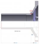
In operation the tube portion of the bearing retainer really just serves as a guide for the throw-out bearing. As such, it shouldn’t have a great deal of force acting on it as it doesn’t transfer power, bear a thrust load, used to mount the transmission, etc. It can have a bending moment or off-axis force from the throw-out bearing, most likely due to a bad pressure plate that is forcing the throw-out bearing into a cocked position. This can happen with both spring-type and a diaphragm-type pressure plates and I’ve replaced a few for that exact issue. That being said, if the pressure plate is bad and causing the throw-out bearing to be cocked around the pressure plate needs to be replaced anyway and will cause the clutch to stick. You cannot blame a bad pressure plate on the bearing retainer. Back to the main point, I analyzed the model (using Finite Element Analysis, FEA) by approximating the engagement area of the throw-out bearing and applied loads, re-ran the FEA on models with different sized seals and seal depths. I used typical assumptions in the FEA such as mild steel, constant material properties, etc. Given the shape and complexity I did not do a textbook style pen and paper analysis. After all, I pay about $1400 to maintain my CAD software, so I should get some use out of it.

The forces that might act on the tube portion of the bearing retainer while not in operation also need to be considered. The engineering analysis for both in and out of operation is similar anyway. So take for example that someone grabs the tube portion of the bearing retainer and the exit flange and lifts the transmission. Bear in mind that I don’t recommend this wouldn’t do this with this heavy of a transmission and it should be lifted by the body as the bearing retainer is not a handle, although it is standard practice for smaller transmissions. Disclaimers aside, you would not want the bearing retainer to bend if you did happen to carry it this way. The results of my FEA made it clear that you could lift this beast by the snout, that it would not plastically deform (permanent) if you did, and that machining the seal pocket did not cause a significant change in strength of the part. And then for the disclaimer, I don’t recommend anyone do anything stupid like drop the transmission out of the back of the truck onto concrete and expect there to be no damage.
Here is a snip of the cross-section of my model with the seal pocket. As you can see, it doesn’t get much thinner than the rest of the part. At first glance, (especially if you look at the big seal assumptions) it would seem that the part is badly compromised by the seal pocket. Careful analysis using modern tools and methods combined with the results of the seal search demonstrate that the addition of the seal is very plausible.

I will post more pics and hopefully a video on YouTube in the next week or so. Also, I plan to have 10 of these available later this week.Bearing Retainer Compromise Cross Section.jpg
 

gringeltaube

Staff Member
Super Moderator
Moderator
Steel Soldiers Supporter
6,882
2,260
113
Location
Montevideo/Uruguay
As you can see, it doesn’t get much thinner than the rest of the part. At first glance, (especially if you look at the big seal assumptions) it would seem that the part is badly compromised by the seal pocket. Careful analysis using modern tools and methods combined with the results of the seal search demonstrate that the addition of the seal is very plausible.
Nice drawing and study! Hopefully it would end with a reliable (and much more affordable solution) but I’m afraid that you are being a bit too optimistic here…?
Your modified bearing retainer(-model) may be acceptable as it looks but the reality is a little different. Even for a seal a bit smaller - 1.88”O.D. x .187”W as you are suggesting, there simply isn’t enough room - or material left. Keep in mind, this is relatively brittle cast iron!

Coming from different manufacturers and made over decades, these parts obviously present some minor variations, mainly around the (outer)flange area. But I’m pretty sure that they all share exactly the same overall length as well as shaft length.

Maybe your drawing was just a quick draft but still, all seems well proportioned and accurate there, except just where the critical area is.
So please, check your measurements – also for the relative position of the input shaft - and then compare with the dimensions given in my drawing, lower half…


2[SUP]nd[/SUP] drawing is just another approach - still trying to (re)use the original part, turned in the lathe to accept some kind of “inserted” seal carrier.


G.
 

Attachments

rustystud

Well-known member
9,071
2,388
113
Location
Woodinville, Washington
I like the look of that seal Gerhard ! Though I really like the idea of a "Steel housing" that Garrett was making. I don't want to be in the middle of Alaska and have my transmission snout break !
 

gringeltaube

Staff Member
Super Moderator
Moderator
Steel Soldiers Supporter
6,882
2,260
113
Location
Montevideo/Uruguay
We have not mentioned yet the option of having this retainer made out of cast iron, same as original but with the correct shape to accommodate that seal.
Anyone here having connections to a good foundry? Or even owning one??
I still think that a batch of say 100 pieces could be sold easily if this proved to be a good quality part, for a cost of $100 each, or maybe less.

Another advantage of having a whole new part machined would be a slightly modified flange in order to completely eliminate the paper gasket and just use Loctite 518 to install it.
On the stock parts that paper gasket (used with or w/o RTV) has always been a bit problematic: 1st, it has to have the exact correct thickness in order to avoid warping of the flange (very common problem!); 2nd, these gaskets tend to "give" ( = loose their original thickness) over time, creating another possible leak spot.
(BTW: I have never used any of the paper gaskets for these Spicers; all three bearing retainers are milled/turned accordingly and then installed with anaerobic sealant.)


G.
 

brianp454

Member
572
11
18
Location
Portland, OR
<--- Enjoying parking in the driveway without any drips151211 Bearing Retainer with Seal 1 Best.jpg151217 M35A2 3053A Leak in Bellhousing 1 Best.jpg151220 M35A2 3053A Install 4 Best.jpg


I purchased an engine rear seal in the event I got the transmission out and found the rear seal was also leaking, yet decided it was not necessary. The leak I've been chasing is from the transmission pouring from the bearing retainer and getting splattered around in there. The grit from the clutch made the oil look dirty, allowing it to be confused with engine oil. When I pulled the ring off of the bellhousing the oil at the bottom was greenish gear oil.

I made an aluminum plate from a piece of scrap and it worked fantastic! I used a new gasket to put the holes in it. I cut little slots in a towel to run the screws through and protect the innards from any crud that may fall. When I was done I took the plate off and carefully removed the towel. Reinstalling the top plate was a 5 minute job provided the 5th reverse gear did not slide back into reverse position on it's own due to the slight tilt. I found having the lift point on center nearly exactly between the two next-to-foremost screws for the top plate held the transmission at nearly the exact proper angle.

I kept the throwout bearing in a ziplock bag and installed it right before pushing the tranny forward into the disc. With a few wiggles and thrusts it went in and we were able to get the screws for the bellhousing started.

I also had a slow leak from the output seal and replaced it while doing all of this. At this rate I might be able to get this beast completely leak free.
 
Last edited:

brianp454

Member
572
11
18
Location
Portland, OR
When I had the tranny out I observed the same thing with a small leak (from valve cover?) coming down the back of the head. It's very light, but there's anothe rleak to run down. Whack a mole of leak fixes continues.

Nicely done. I've got almost 6000 miles on mine with no leaks yet. Headgaskets are seeping and running back to the outside of the bellhousing now though.
 

Jeepsinker

Well-known member
5,341
329
83
Location
Dry Creek, Louisiana
Yeah, it's just irritating. I haven't had this motor installed for very long. Wasn't leaking when it went in. It would probably help if I retorque the heads, but I haven't made a wrench yet.
 
Top
AdBlock Detected

We get it, advertisements are annoying!

Sure, ad-blocking software does a great job at blocking ads, but it also blocks useful features of our website like our supporting vendors. Their ads help keep Steel Soldiers going. Please consider disabling your ad blockers for the site. Thanks!

I've Disabled AdBlock
No Thanks