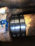
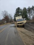
If you look at what is typically done on spring mounted campers, there is always a solid bolted connection at either the front or most rear location and a feature that prevents slewing. Usually they are slide plates.
Below are two references:
View attachment 913450View attachment 913451
in fact, in many place it is illegal not to have those features.
If you were to swerve, your whole box could swing to the side and you will get a slide hammer effect, wich may overload your bolts. Also, the slewing action can zipper your bolts, that is why they always have a guide plate. I would seriously consider adjusting your design. What you have is fine for slow, but get moving fast, inertia may not play nice.